
Springs
Check for corrosion, cock and force at the specified height. Any visible pitting is cause for replacing the valve spring. Significant corrosion can cause premature failure. If the spring is cocked more than .030", discard it. It will cause uneven wear on the valve stem and face and the valve guide. The specifications we use for minimum force are: '33-48 37 lbs @ 2 1/8", '49-51 40 lbs @ 2 1/8", '51-53 39 lbs @ 1 57/64". These are from 1940 and 1953 Motor's Auto Repair Manuals.
The late springs are shorter and are checked at a shorter height to accommodate the two piece spring retainers which allowed valve rotation. This setup does not accommodate the higher lift hot rod cams, although lifts of up to about .350" are usually OK. Check for coil bind.
Spring Retainers
Seldom do you have to replace spring retainers except to change type. Occasionally, they will sustain mechanical damage during tear down. Some of the new replacement 49-51 spring retainers have improper angles and/or rough machining in the split lock area. Check this; just because parts are new does not mean that they are right. The 32-48 retainers are less critical in this area.
Split Locks 49-53 only
Split locks may show wear but are typically reusable. They are inexpensive to replace, even with modern hardened split locks.
Guides
Check for the mechanical condition in the guide retainer groove and in the groove for the removal tool. 32-48 split guides are difficult to check for stem to guide clearance. If you put a test valve in the split guide, and hold the halves oriented correctly, you may lightly tighten them in a vise to check clearance with a dial indicator. They sometimes have as much as .007" clearance with all new parts. We try to hold a maximum of .005", especially on intake valves.
The 49-53 solid guides are much easier to check; they can be held in a vise and checked with the dial indicator. New parts usually yield .002 to .003" clearance, we use a wear limit of .005".
Some guide bores in the block are oversize from chemical stripping or other causes. If guides are loose in the guide bores the guides can be plated with copper.
For some high performance engines, guides are machined on the top to promote more airflow. Sometimes this is done with the guide bonded in place with Loctite. These guides would then be dedicated to that port in the machined orientation.
Guide Locks
These are usually damaged beyond use during teardown; replace them.
Machining
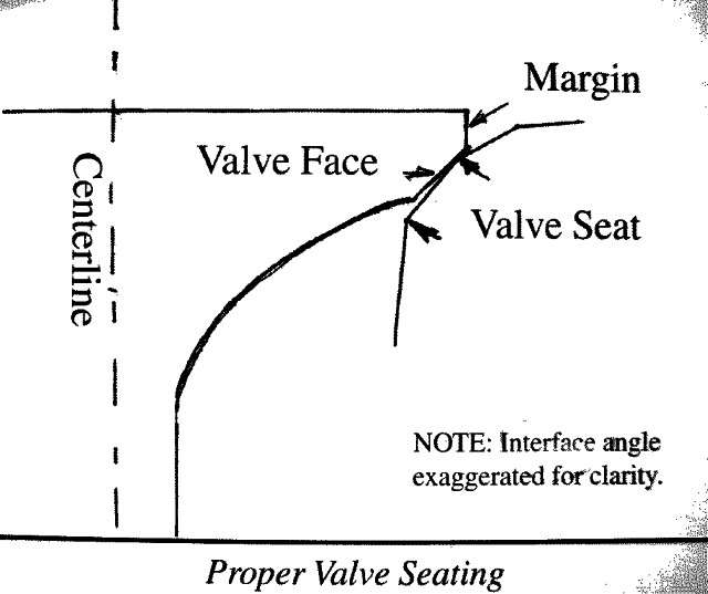
Current practice generally is to allow between ½ and I degree of interference between the valve face angle and the valve seat angle. The stated angle for the valve face is smaller than for the valve seat, resulting in line contact at the top of the valve seat surface. This, when done properly, gives a gas tight seal without lapping.
If you must lap, remove all traces of compound before assembly. This is not easy to do because the lapping compound panicles are actually imbedded in the metal.
Grinding of valve seats is typically done with three or more stones, each with a different angle. The top "corner "between the seat angle (usually 45 degrees) and the top angle (usually 30 degrees) should be under the head of the valve, falling near the outside of the face. The inside angle stone(s) (60-75 degrees) then narrow the seat to the specified width.
There are now some cutters that cut all the angles at the same time.
For use with unleaded gasoline, the exhaust valve seats should be of a hard, tough material. Many of the '48 and earlier already have these, as do some of the '49-'53. The intake seats may be cast iron and the stock or normal aftermarket replacement valves are fine for unleaded fuel.
Next issue we will talk about assembly.